Instructions Manual

Overview

Muz-mo is a biofeedback device intended as an aid for patients exercising under the guidance of their physiotherapist or doctor. It is of particular value to patients recovering from stroke or brain injury.

By giving an audible signal when a patient achieves or exceeds a set movement, Muz- mo gives them encouragement and assurance that they are moving correctly. Such feedback can enable patients to continue to exercise without needing the therapist’s constant close supervision. This can greatly increase the amount of exercise undertaken and potentially benefit recovery.

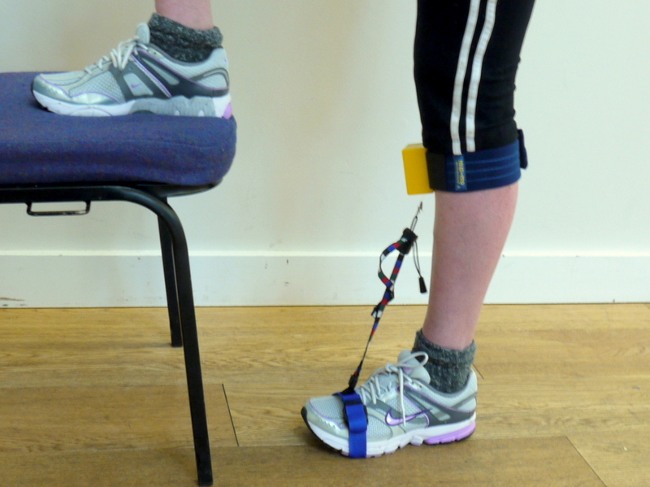
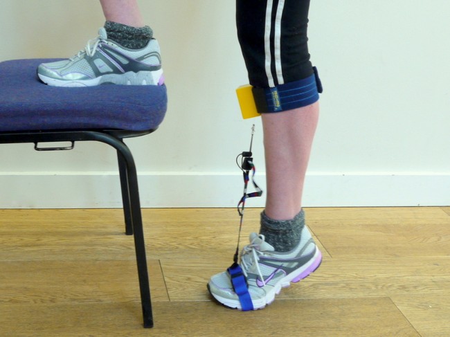
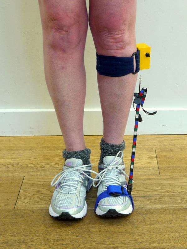
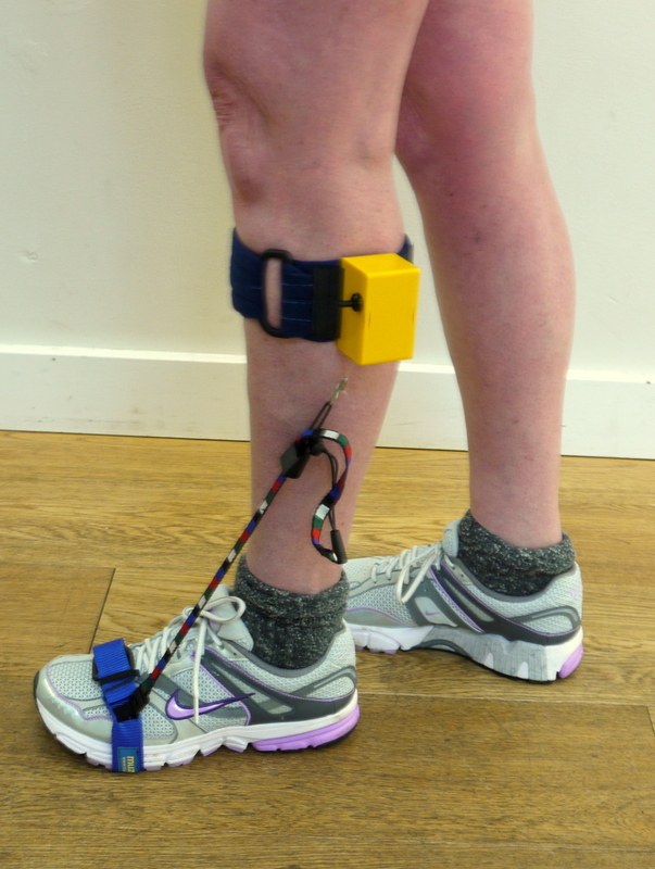
Muz-mo can be used to monitor the movement of a foot, hand, leg or arm relative to another part of the body or to a fixed object. It can be used in a wide range of activities including walking.

The audible signal removes the need for the patient to try to view the movement, which at times can be very difficult; thus allowing the patient to adopt an appropriate posture and balance.

Muz-mo can be adjusted so that the movement target can be easily and finely varied to meet the patient's needs as they progress.

A Muz-mo unit is designed to be used many times by one patient during their rehabilitation period.

Package Contents

package-contents

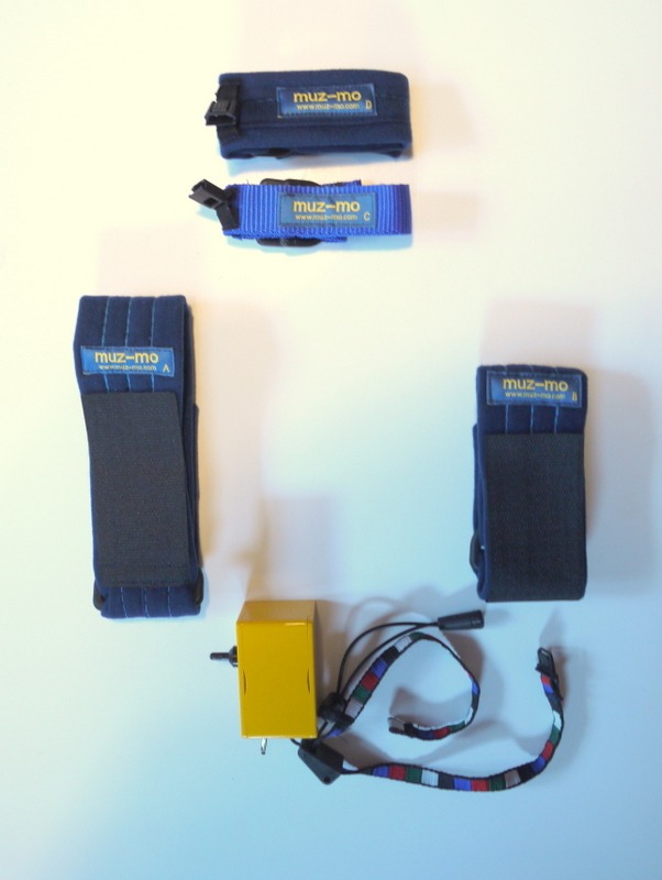
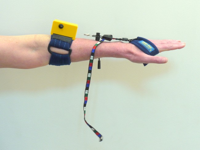
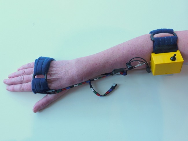
Narrow, padded blue strap (labelled 'D') normally used in hand or arm exercises

Blue webbing strap (labelled 'C') to be worn over shoe or trainer for foot or walking exercises

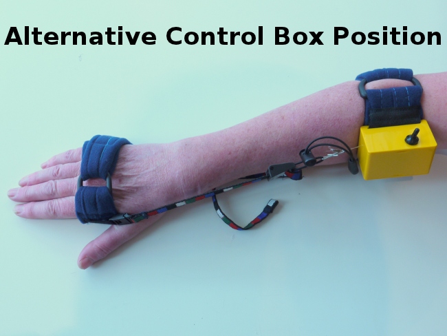
Long blue padded strap (labelled 'A') for attaching control box

Short blue padded strap (labelled 'B') for attaching control box

Yellow control box with multi-coloured webbing and elastic link attached

Operation

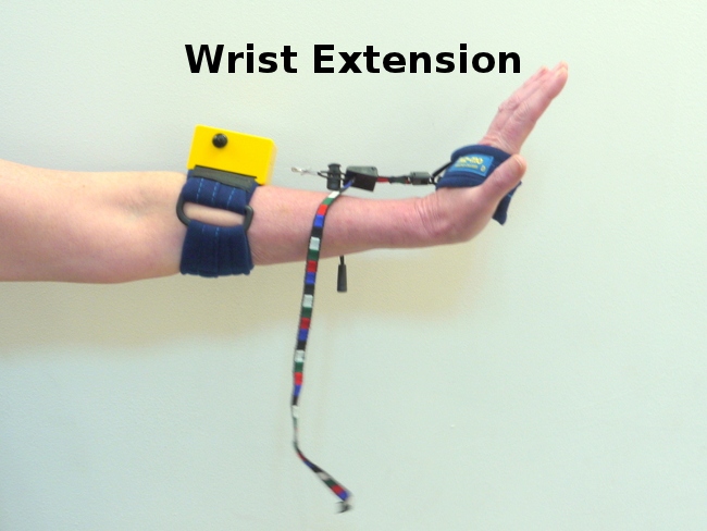
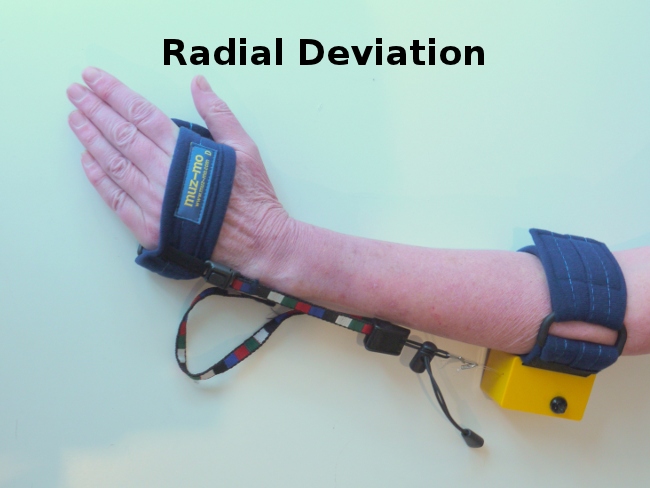
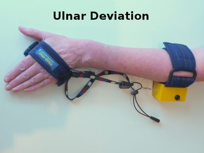
The control box switch can be set so the signal sounds when the monitored limb is moved towards the box (mode 1) or when it is moved away from the box (mode 2). The switch should be left in the central position (0), turning the device off, when it is not in use.

    • Attach the yellow control box to a padded strap. The longer strap ‘A’ is normally used to locate the control box on an adult leg. There is a wide, black 'Velcro' tape with one end sewn to the strap. Thread this through the long slot at the control box back and press firmly onto the strap surface so that the tape's hook surface securely engages and the box is firmly held.
    • Position the control box as required: for example, below the knee for foot exercises or on the upper part of the forearm for hand exercises. Wrap the strap around the limb, put one end through the 'D' ring in the other, pull it tight, double it back and press the 'Velcro' firmly onto the blue strap material to hold it securely in place. Ensure the correct location and orientation for the relevant exercise. Do not over- tighten.
    • If so required for a particular exercise the control box can also be attached to a fixed location such as a bed head or wheelchair arm.
operation-important-note

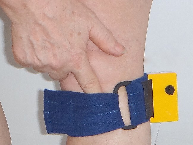
IMPORTANT: So that they do not slip out of position, both control box and locator need to be held firmly in place but straps must not be over-tightened so as to restrict blood flow. When wrapping a strap around a limb, check you can easily insert a finger between the strap and the body to ensure the strap is not over tight. Do not use the straps over any wounds, broken or irritated skin. Always ensure no part of a strap or link trails on the ground to cause a trip hazard.

    • Attach strap ‘D’ to hand or limb to be monitored or strap ‘C’ to shoe. Ensure the link locator is positioned correctly for the exercise movement (see below for examples).
    • Using the control box switch, choose mode 1 or mode 2.
    • Feeding the coloured tape through the tape lock alters the size of the loop in the middle of the tape. This changes the effective length of the link.
    • Clip the link locator attachment to the link locator on strap ‘C’ or ‘D’. Increase the link length (reduce the loop) as necessary to do this.
    • Move the limb to the movement target position. Feed the coloured tape through the tape lock to increase or reduce the loop until the signal is switched (on or off as required) when the limb is at the target movement position.

Note: Usually attaching and adjusting Muz-mo can be done with the patent seated. It may be helpful to place a wedge or other support under the foot or limb to support it  the target position while adjustments are being made.

  • Incremental changes to the movement target (to increase or decrease the amount of movement required to activate the signal) can be made by feeding the coloured tape through the tape lock to make small changes to the loop length and the overall link length. Muz-mo can be used to signal very small movements if that is what is needed at first.
  • Increasing the length of the elastic link section increases the freedom of movement the patient may have without risk of the control box or straps being pulled out of place. Reducing the elastic link section increases the device’s sensitivity. Keep the elastic link section to the minimum appropriate for the activity but remember that very limited, or no, elastic section may result in damage to the equipment. The elastic section's unstretched length should be never less than 20mm.

Example – use in heel raise exercise:

muz-mo-heal-raise-exercise1 muz-mo-heal-raise-exercise2
  • The device should be attached as described in the above instructions
  • The control box should be located on the front of the lower leg a little below the knee.
  • Strap 'C' should be used over a shoe or trainer around the ball of the foot with the locator positioned on the central line of the foot. After tightening, any trailing strap end should be turned back over the D-rings and threaded under the elastic retaining loop to avoid any trip hazard.
  • The control box switch should be set to 2.
  • The link clip should be attached to the link locator on strap 'C' and adjusted until the signal sounds when the heel is raised the required amount.

Example - Use in foot eversion/dorsiflexion exercises:

  • The device should be attached and adjusted as described in the instructions.
  • The control box should be located on the outside of the upper calf towards the back of the calf to ensure a clear signal from the raising and moving the lateral side of the foot outwards rather than from simply raising the foot.
  • Strap ‘C’ should be used over a shoe or trainer to position the link locator on the edge of the foot at the base of the small toe.
  • The device may be used when the patient is sitting, standing or walking. If used in walking the signal may sound once in swing phase (as the foot moves forward) to indicate achievement of the foot eversion target and once in static phase if the knee is bent. Note this may be used to help the patient practise avoiding over extending the knee.
muz-mo-foot-eversion-dorsiflexion-exercise1 muz-mo-foot-eversion-dorsiflexion-exercise2

Example - Use in hand exercises:

muz-mo-wrist-extension-exercise1 muz-mo-wrist-extension-exercise2
  • The device should be attached and adjusted as described in the instructions.
  • For exercises to improve wrist extension, the control box should be located on the upper part of the forearm and strap 'D' fitted across the palm of the hand with the locator positioned on the back of the hand. The link between the hand strap and the control box should be directly along the line of the forearm and not diagonal.
  • For exercises to improve radial and ulnar deviation, Strap 'D' should be fitted around the hand at the knuckles with the link locator to the right or left of the hand. The control box can be located on either the inside or outside of the forearm but should be aligned with the locator position on the hand strap 'D.
muz-mo-hand-exercise2 muz-mo-radial-deviation-exercise
muz-mo-ulnar-deviation-exercise muz-mo-alternative-control-box-position

We welcome any comments or observations arising from your experience of using
Muz-mo. Please email: info@muz-mo.com

Warning/Cautions

  • If the patient has any hearing impairment the health professional should ensure they are able to hear the signal.
  • The battery should be removed when the device is not to be used for a long period of time.
  • Do not immerse the control box in water or other liquids.
  • The Muz-mo is intended for single patient use with one patient using the same device many times during their rehabilitation period. Re-use of the equipment by different patients can increase the risk of cross infection.
  • So that they do not slip out of postion, both control box and the locator need to be held firmly in place but straps must not be overtightened so as to restrict blood flow. When wrapping a strap around a limb, check you can easily insert a finger between the strap and the body to ensure the strap is not overtight.
  • Do not use the straps over any wounds, broken or irritated skin.
  • Always ensure no part of a strap or link trails on the ground to cause a trip hazard.

Battery

The 9V PP3 battery should provide at least 40 hours of continuous signal sounding (many more hours of Muz-mo use). The battery should be checked prior to use by moving the switch to the mode 2 position with no tension applied to the link: the signal will sound if the battery has sufficient charge.

Power Saving

To save battery power, the device should be turned off when not in use.

Maintenance

Cleaning

  • If necessary, the box surface may be wiped clean with a cloth or tissue moistened with any common, commercially available water based or alcohol based cleaning or antibacterial fluid.
  • After being separated from the control box and link, the straps may be washed clean, by hand or machine, in warm water and gentle detergent, rinsed and dried.
  • Do not immerse the control box in water or other liquid.
  • The device is not designed to be fully sterilized by heat or other means.
muz-mo-replacing-battery

Replacing the battery

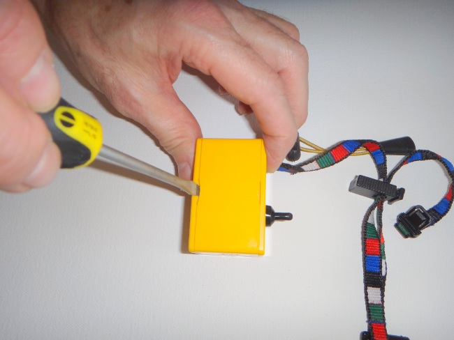
If the buzzer ceases to operate when a muz-mo unit is switched on, the battery may need replacing. Muz-mo uses one 9 Volt PP3 type alkaline battery. Carefully lever up the lid using a flat screwdriver inserted into the two slots in the control box front face (see picture) and gently pull off the lid. The battery may then be pulled out and the contacts unclipped. After replacing with a new battery, gently press the lid back on to clip it into position. Press the box sides to fully seat the lid into the locating grooves.

Specifications

Operating Voltage 9v
Operating Temperature 10C to 40C
Battery Storage Temperature 10C to 25C
Sound output at 20cm2 >75dB
Tone Continuous
Battery Life 40 hours continuous sounding signal
Control Box Dimensions 65mm x 40mm x 40mm
Weight of control box, link, strap A andstrap C 148g
Weight of carrying box and contents 570g

Servicing and spares

If your unit requires servicing or if you would like to obtain spare parts, or require straps of a different length to the ones provided, then please contact your authorised distributor or info@muz-mo.com

Catalogue NumberDescription
M1A Strap A
M2B Strap B
M3C Strap C
M4D Strap D
M5L Link
M6X Link
M5L Customised strap- please specify A,B,C, or D and length required
M7EL Elastic loop for link
M8RSL Return silicone loop